Honda Fit/Jazz - CVT System Description (CVT)
CVT System Description
General Operation
The continuously variable transmission (CVT) is an electrically controlled automatic transmission with drive and driven pulleys, and steel belt. The CVT provides non-stage speeds forward and 1 reverse. The entire unit is positioned in line with the engine.
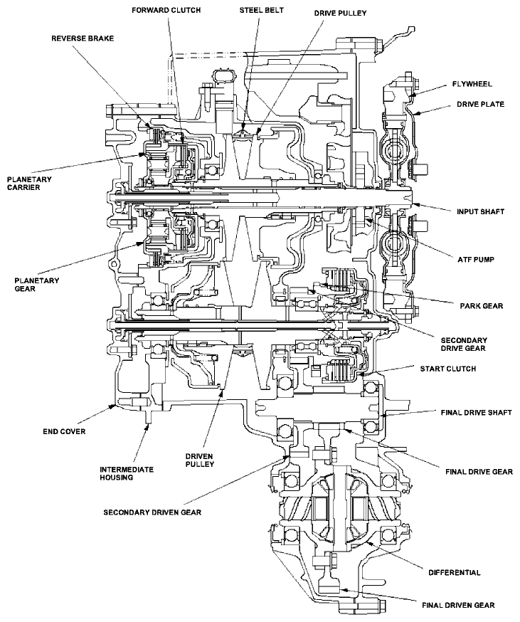
Transmission
Around the out side of the flywheel is a ring gear which meshes with the starter pinion when the engine is being started. The transmission has four parallel shafts: the input shaft, the drive pulley shaft, the driven pulley shaft, and the final drive shaft. The input shaft is in line with the engine crankshaft. The drive pulley shaft and driven pulley shaft consist of movable and fixed face pulleys. Both pulleys are linked by the steel belt.The input shaft includes the sun gear and planetary gears with carrier. The drive pulley shaft includes the drive pulley and forward clutch. The driven pulley shaft includes the driven pulley, start clutch, and the secondary driven gear which is integral with the park gear. The final drive shaft is positioned between the secondary drive gear and the final driven gear. The final drive shaft includes the final drive gear and the secondary driven gear which serves to change the rotation direction, because the drive pulley shaft and driven pulley shaft rotate the same direction. When certain conditions of the planetary gears in the transmission are engaged by the forward clutch and the reverse brake, power is transmitted from the drive pulley shaft to the driven pulley shaft to provide L, S, D, and R positions.
Electronic Control
The electronic control system consists of the powertrain control module (PCM), sensors, and solenoid valves. Shifting is electronically controlled for comfortable driving under all conditions. The PCM is located below the dashboard, behind the glove box.Hydraulic Control
The valve bodies include the main valve body, the ATF pump body, the control valve body, the ATF pass body, and the manual valve body. The ATF pump body is bolted on the main valve body. The main valve body is bolted on the flywheel housing. The control valve body is positioned outside of the transmission housing. The ATF pass body is positioned on the main valve body, and connected hydraulic circuit between the control valve body, main valve body and internal hydraulic circuit. The manual valve body is positioned on the intermediate housing.The ATF pump is the trochoid type, and the inner rotor is splined with the input shaft. The pulleys and clutches receive fluid from their respective feed pipes, and the reverse brake receives fluid from internal hydraulic circuit.
Shift Control
The PCM controls to shift pulley ratio the solenoids, which receiving input signal from the various sensors and switches located throughout the vehicle. The PCM actuates the CVT speed change control valve and CVT pulley pressure control valve to change pulley control pressure. The drive pulley control pressure is applied to the drive pulley, and the driven pulley control pressure is applied to the driven pulley, and pulley ratio is changed to their effective ratio.Gear Selection
The shift lever has six positions: P PARK, R REVERSE, N NEUTRAL, D DRIVE, S SECOND, and L LOW.
| Position | Description |
|---|---|
| P PARK | Front wheels locked; park pawl engaged with park gear on the driven pulley shaft. The start clutch and forward clutch released. |
| R REVERSE | Reverse; reverse brake engaged. |
| N NEUTRAL | Neutral; the start clutch and forward clutch released. |
| D DRIVE | General driving; the transmission automatically adjusts to keep the engine at the best speed for driving under all conditions. |
| 2 SECOND | For rapid acceleration; the transmission selects a wider range of ratios to give better acceleration. |
| L LOW | For engine braking and power for climbing; the transmission shifts into the lowest range of the ratios. |
Starting is possible only in P and N positions because of a slide-type neutral-safety switch.
Automatic Transaxle (A/T) Gear Position Indicator
The A/T gear position indicator in the instrument panel shows what position has been selected without looking down at the console.Clutches/Reverse Brake/Planetary Gear/Pulleys
Clutches/Reverse Brake
The Multi Matic uses the hydraulic-actuated clutches and brake to engage and disengage the transmission gears. When hydraulic pressure is introduced into the clutch drum and the reverse brake piston cavity, the clutch piston and the reverse brake piston move. This presses the friction discs and steel plate together, locking them so they don't slip. Power is then transmitted through the engaged clutch pack to its hub-mounted gear, and through engaged ring gear to pinion gears.Likewise, when the hydraulic pressure is bled from the clutch pack and reverse brake piston cavity, the piston releases the friction discs and the steel plates, and they are free to slid past each other. This allows the gear to spin independently on its shaft, transmitting no power.
Start Clutch
The start clutch engages/disengages the secondary drive gear, and is located at the end of the driven pulley shaft. The start clutch is supplied hydraulic pressure by its ATF feed pipe within the driven pulley shaft.Forward Clutch
The forward clutch engages/disengages the sun gear, and is located at the end of the drive pulley shaft. The forward clutch is supplied hydraulic pressure by its ATF feed pipe within the drive pulley shaft.Reverse Brake
The reverse brake locks the planetary carrier in R position, and is located inside the intermediate housing around the planetary carrier. The reverse brake discs are mounted to the planetary carrier and the reverse brake plates are mounted on the intermediate housing. The reverse brake is supplied hydraulic pressure by a circuit connected to the internal hydraulic circuit.Planetary Gear
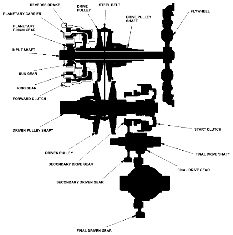
The planetary gear consists of the sun gear, planetary pinion gears, and ring gear. The sun gear is connected to the input shaft with splines. The pinion gears are mounted on the planetary carrier. The planetary carrier is located on the end of the input shaft, over the sun gear. The ring gear is located in the planetary carrier, and connected to the forward clutch drum. The sun gear inputs the engine power via the input shaft to the planetary gears, and the carrier outputs the engine power. The planetary gear mechanism is only used for switching the rotation direction of the pulley shafts. In D, S, and L position (forward range), the pinion gears don't rotate and revolve around the sun gear, so the carrier rotates. In R position (reverse range), the reverse brake locks the planetary carrier, and the sun gear drives the pinion gears to rotate. The pinion gears rotate, but don't revolve around the sun gear. The pinion gears drive the ring gear in the opposite direction from the rotation direction of the sun gear.Pulleys
Each pulley consists of a movable face and a fixed face, and the effective pulley ratio changes with engine speed. The drive pulley and the driven pulley are linked by the steel belt.To achieve a low pulley ratio, high hydraulic pressure works on the movable face of the driven pulley and reduces the effective diameter of the drive pulley, and a lower hydraulic pressure works on the movable face of the driven pulley to eliminate the steel belt slippage. To achieve a high pulley ratio, high hydraulic pressure works on the movable face of the drive pulley and reduces the effective diameter of the driven pulley, and low hydraulic pressure works on the movable face of the driven pulley to eliminate the steel belt slippage.
Transmission Cutaway View
Power Flow
P Position
Hydraulic pressure is not applied to the start clutch, forward clutch, and the reverse brake. Power is not transmitted to the secondary drive gear. The secondary drive gear is locked by the park pawl interlocking the park gear.
N Position
Engine power transmitted from the flywheel drives the input shaft, but the hydraulic pressure is not applied to the forward clutch and reverse brake. Power is not transmitted to the drive pulley shaft. Also hydraulic pressure is not applied to the start clutch.
D, S, and L Position (Forward Range)
- Forward clutch engages.
- Reverse brake releases.
- Start clutch engages.
- Hydraulic pressure is applied to the forward clutch and the start clutch, and the sun gear drives the forward clutch.
- The forward clutch drives the drive pulley shaft, which drives the driven pulley shaft linked by the steel belt.
- The driven pulley shaft drives the secondary drive gear via the start clutch.
- Power is transmitted to the secondary driven gear and final drive gear, which in turn drives the final driven gear.

Power Flow (cont'd)
R Position (Reverse Range)
- Forward clutch releases.
- Reverse brake engages.
- Start clutch engages.
- Hydraulic pressure is applied to the reverse brake and the start clutch, and the planetary carrier locks with the reverse brake.
- The sun gear drives the planetary pinion gears to rotate, and the planetary pinion gears drive the ring gear in the opposite direction from the rotation direction of the sun gear.
- The ring gear drives the drive pulley shaft via the forward clutch drum, and drive pulley shaft drives the driven pulley shaft linked by the steel belt.
- The driven pulley shaft drives the secondary drive gear via the start clutch.
- Power is transmitted to the secondary driven gear and final drive gear, which in turn drives the final driven gear.
Electronic Control System
Functional Diagram
The electronic control system consists of the powertrain control module (PCM), sensors, and solenoid valves. Shifting is electronically controlled for comfortable driving under all conditions.
The PCM inputs signals from the sensors, switches, and other control units, perform processing data, and outputs signals for engine control system and CVT control system. The CVT control system includes shift control/pulley pressure control, start clutch pressure control, reverse inhibitor control, and also a grade logic control is stored in the PCM. The PCM actuates the solenoid valves to control shifting transmission pulley ratios.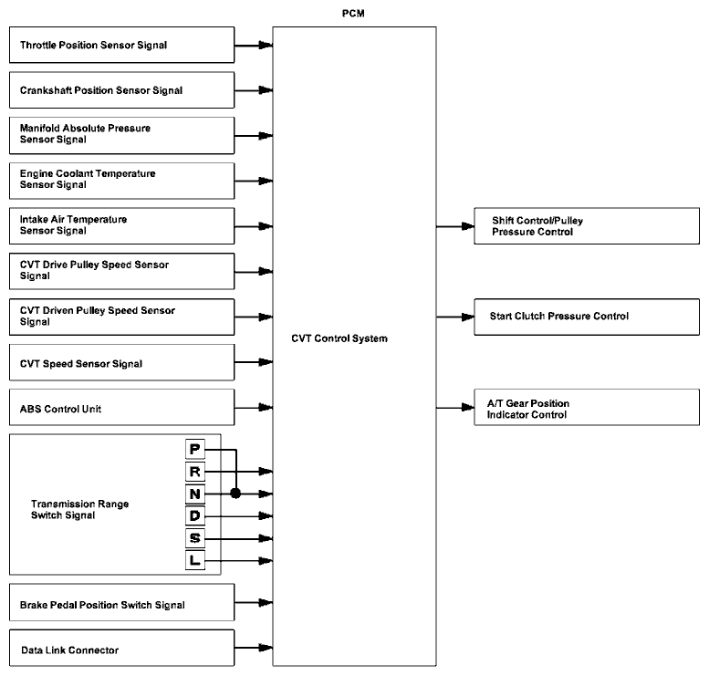
Electronic Control System (cont'd)
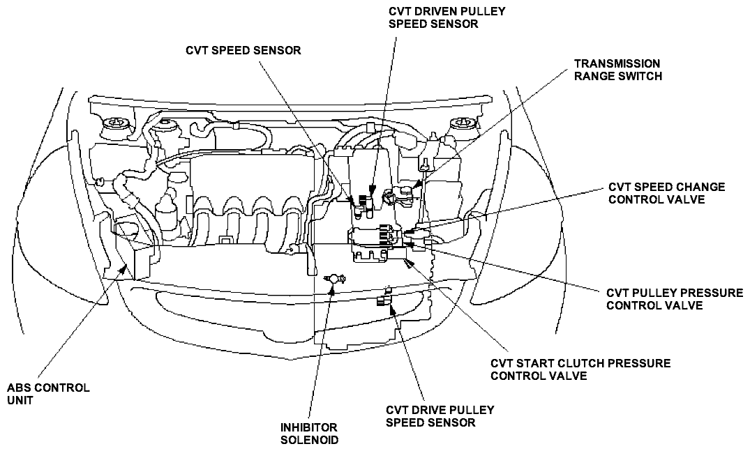
Electronic Controls Location

Shift Control/Pulley Pressure Control
The PCM compares actual driving conditions with memorized driving conditions to control shifting, and instantly determines a ratio of drive pulley and driven pulley by various signals sent from sensors and switches. The drive pulley drives the driven pulley by the steel belt at a ratio between 2.367-0.407 in non-stage in the D position. In the R position, the ratio is set to 1.326 when pressing the accelerator, and to 2.367 when the accelerator released. When the pulley ratio is low (vehicle speed is low), the driven pulley receives high pulley pressure to hold large diameter, and the drive pulley receives low pressure to hold diameter of proportion to the driven pulley. When the pulley ratio is high (vehicle speed is high), the driven pulley receives low pressure, and drive pulley receives high. The PCM actuates the pulley pressure control valves to regulate optimum pulley pressure to the pulleys for reducing belt slippage and long belt life.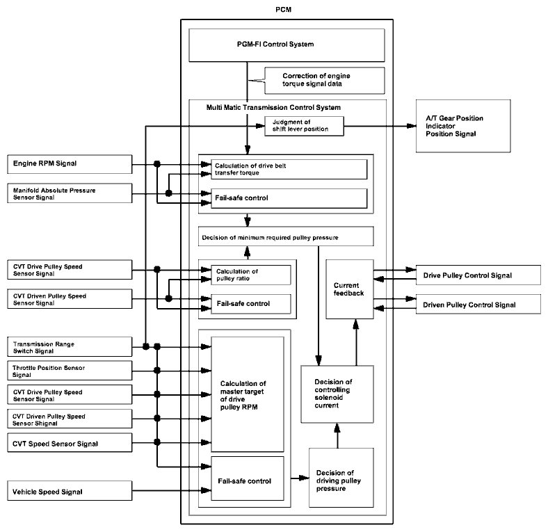
Electronic Control System (cont'd)
Start Clutch Pressure Control
Hydraulic-controlled start clutch works smooth starting-off and creeping in D, S, L, and R positions like the torque converter. The PCM inputs signals from the sensors and switches, and actuates the start clutch pressure control valve to regulate the start clutch pressure.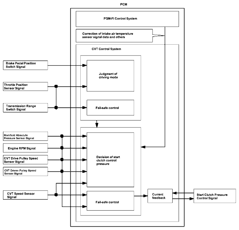
PCM Electrical Connections

Electronic Control System (cont'd)
PCM Inputs and Outputs

| Terminal Number | Wire Color | Signal | Description | Measuring Conditions/Terminal Voltage |
|---|---|---|---|---|
| A2 | YEL/BLK | IGP2 | Power supply circuit from main relay | With ignition switch ON (II): Battery voltage With ignition switch OFF: 0 V |
| A3 | YEL/BLK | IGP1 | Power supply circuit from main relay | With ignition switch ON (II): Battery voltage With ignition switch OFF: 0 V |
| A4 | BLK | PG2 | Ground | |
| A5 | BLK | PG1 | Ground | |
| A10 | GRN/BLK | SG2 | Sensor ground | |
| A11 | GRN/WHT | SG1 | Sensor ground | |
| A18 | BLU/WHT | VABS | Vehicle speed sensor signal input | With ignition switch ON (II): About 5 V With ignition switch OFF: 0 V |
| A20 | YEL/GRN | VCC2 | Power supply circuit for sensors | With ignition switch ON (II): About 5 V With ignition switch OFF: 0 V |
| A21 | YEL/RED | VCC1 | Power supply circuit for sensors | With ignition switch ON (II): About 5 V With ignition switch OFF: 0 V |
| A23 | BRN/BLK | LG2 | Ground | |
| A24 | BRN/BLK | LG1 | Ground |
| Terminal Number | Wire Color | Signal | Description | Measuring Conditions/Terminal Voltage |
|---|---|---|---|---|
| B7 | GRN/WHT | DN LS + | CVT pulley pressure control valve power supply positive electrode | With ignition switch ON (II): Pulsing signal |
| B16 | YEL | SC LS + | CVT start clutch pressure control valve power supply positive electrode | With ignition switch ON (II): Pulsing signal |
| B24 | BLU/WHT | DR LS + | CVT speed change control valve power supply positive electrode | With ignition switch ON (II): Pulsing signal |
| Terminal Number | Wire Color | Signal | Description | Measuring Conditions/Terminal Voltage |
|---|---|---|---|---|
| C1 | PNK/BLK | DN LS - | CVT pulley pressure control valve power supply negative electrode | With ignition switch ON (II): Pulsing signal |
| C6 | GRN/BLK | SOL INH | Inhibitor solenoid control | With ignition switch ON (II): Battery voltage With ignition switch OFF: 0V |
| C7 | RED/BLU | NDR | CVT drive pulley speed sensor signal input | With ignition switch ON (II): 0 V or about 5 V With engine at idle in N position: About 2.5 V |
| C8 | PNK/BLU | SC LS - | CVT start clutch pressure control valve power supply negative electrode | With ignition switch ON (II): Pulsing signal |
| C9 | BLU/WHT | ATP S | Transmission range switch S position input | In S position: 0 V In other than S position: About 10 V |
| C10 | WHT | ATP R | Transmission range switch R position input | In R position: 0V In other than R position: About 10 V |
| C11 | BLU | ATP L | Transmission range switch L position input | In L position: 0V In other than L position: About 10 V |
| C12 | LT GRN | ATP NP | Transmission range switch P and N position input | In P and N position: 0V In other than P and N position: About 5 V |
| C15 | WHT | NDN | CVT driven pulley speed sensor signal input | With ignition switch ON (II): 0 V or about 5 V With engine at idle in N position: About 2.5 V |
| C16 | GRN/YEL | DR LS - | CVT speed change control valve power supply negative electrode | With ignition switch ON (II): Pulsing signal |
| C20 | PNK | ATP D | Transmission range switch D position input | IN D position: 0V In other than D position: About 8 V |
| C22 | WHT/RED | VEL1 | CVT speed sensor signal input | With ignition switch ON (II): 0 V or about 5 V With driving (front wheels rotating): About 2.5 V |
| Terminal Number | Wire Color | Signal | Description | Measuring Conditions/Terminal Voltage |
|---|---|---|---|---|
| E11 | PNK | D IND | D indicator control | When ignition switch is first turned ON (II): About 6 V for 2 seconds In D position: About 6 V |
| E22 | WHT/BLK | BK SW | Brake pedal position switch signal input | Brake pedal pressed: Battery voltage Brake pedal released: 0 V |
| E29 | BRN | SCS | SCS terminal signal input | With ignition switch ON (II)
|
Hydraulic Control
The hydraulic control system is controlled by the ATF pump, the valves, and the solenoids. The ATF pump is driven by the input shaft. Fluid from the ATF pump flows through the PH regulator valve to maintain specified pressure to the drive pulley, the driven pulley, and the manual valve.
The valve bodies include the main valve body, the ATF pump body, the control valve body, and the manual valve body. The main valve body is bolted on the flywheel housing. The ATF pump body is bolted on the main valve body. The control valve body located outside of the transmission housing. The manual valve body is bolted on the intermediate housing.
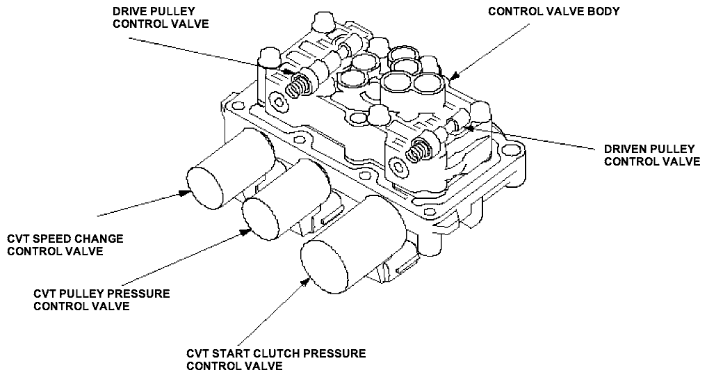
Control Valve Body
The control valve body is located outside of the transmission housing, and contains the CVT speed change control valve, the CVT pulley pressure control valve, the CVT start clutch pressure control valve, the drive pulley control valve, and the driven pulley control valve.
- CVT Speed Change Control Valve
The CVT speed change control valve consists of the linear solenoid and the spool valve, and is controlled by the PCM. The CVT speed change control valve supplies the drive pulley control pressure (DRC) to the drive pulley control valve. - CVT Pulley Pressure Control Valve
The CVT pulley pressure control valve consists of the linear solenoid and the spool valve, and is controlled by the PCM. The CVT pulley pressure control valve supplies the driven pulley control pressure (DNC) to the driven pulley control valve. - CVT Start Clutch Pressure Control Valve
The CVT start clutch pressure control valve consists of the linear solenoid and the spool valve, and is controlled by the PCM. The CVT start clutch pressure control valve regulates the volume of the start clutch pressure (SC) according to the throttle opening, and supplies the start clutch pressure (SC) to the start clutch. - Drive Pulley Control Valve
The drive pulley control valve regulates the drive pulley pressure (DR), and supplies to the drive pulley. - Drive Pulley Control Valve
The driven pulley control valve regulates the driven pulley pressure (DN), and supplies to the driven pulley.
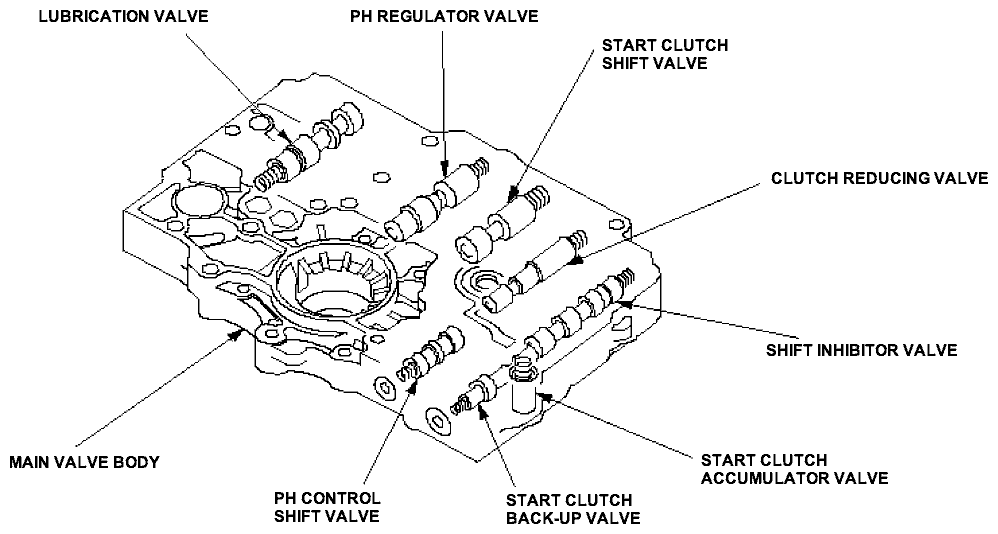
Main Valve Body
The main valve body contains the PH regulator valve, the PH control shift valve, the clutch reducing valve, the shift inhibitor valve, the start clutch accumulator valve, the start clutch shift valve, the start clutch back-up valve, and the lubrication valve.
- PH Regulator Valve
The PH regulator valve maintains hydraulic pressure supplied from the ATF pump, and supplies PH pressure to the hydraulic control circuit and the lubrication circuit. PH pressure is regulated at the PH regulator valve by the PH control pressure (PHC) from the PH control shift valve. - PH Control Shift Valve
The PH control shift valve supplies PH control pressure (PHC) to the PH regulator valve to regulate PH pressure in accordance with drive pulley control pressure (DRC) and driven pulley control pressure (DNC). - Clutch Reducing Valve
The clutch reducing valve receives PH pressure from the PH regulator valve and regulates the clutch reducing pressure (CR). - Shift Inhibitor Valve
The shift inhibitor valve switches the fluid passage to switch the start clutch control from electronic control to hydraulic control when the electronic control system breakdown is occurred. - Start Clutch Accumulator Valve
The start clutch accumulator valve stabilizes the hydraulic pressure that is supplied to the start clutch. - Start Clutch Shift Valve
When the electronic control system breakdown is occurred, the start clutch shift valve receives the shift inhibitor pressure (SI), and covers the bypass circuit of the lubrication pressure (LUB) to the start clutch back-up valve. - Start Clutch Back-up Valve
The start clutch back-up valve supplies the clutch control B pressure (CCB) to control the start clutch when the electronic control system breakdown is occurred. - Lubrication Valve
The lubrication valve stabilizes the lubrication pressure to the internal hydraulic circuit.
Hydraulic Control (cont'd)
ATF Pump Body
The ATF pump body is bolted on the main valve body, and the ATF pump is trochoid type. The inner rotor is splined with the input shaft, and driven by the input shaft. The ATF pump supplies hydraulic pressure to the PH regulator valve.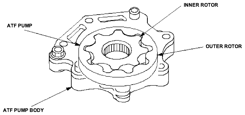
Manual Valve Body
The manual valve body is bolted on the intermediate housing, and contains the manual valve and the reverse inhibitor valve.
- Manual Valve
The manual valve mechanically uncovers/covers the fluid passage according to the shift lever position. - Reverse Inhibitor Valve
The reverse inhibitor valve is controlled by the reverse inhibitor pressure (RI) from the inhibitor solenoid. The reverse inhibitor valve intercepts the hydraulic circuit to the reverse brake while the vehicle is moving forward at speed over about 6 mph (10 km/h).

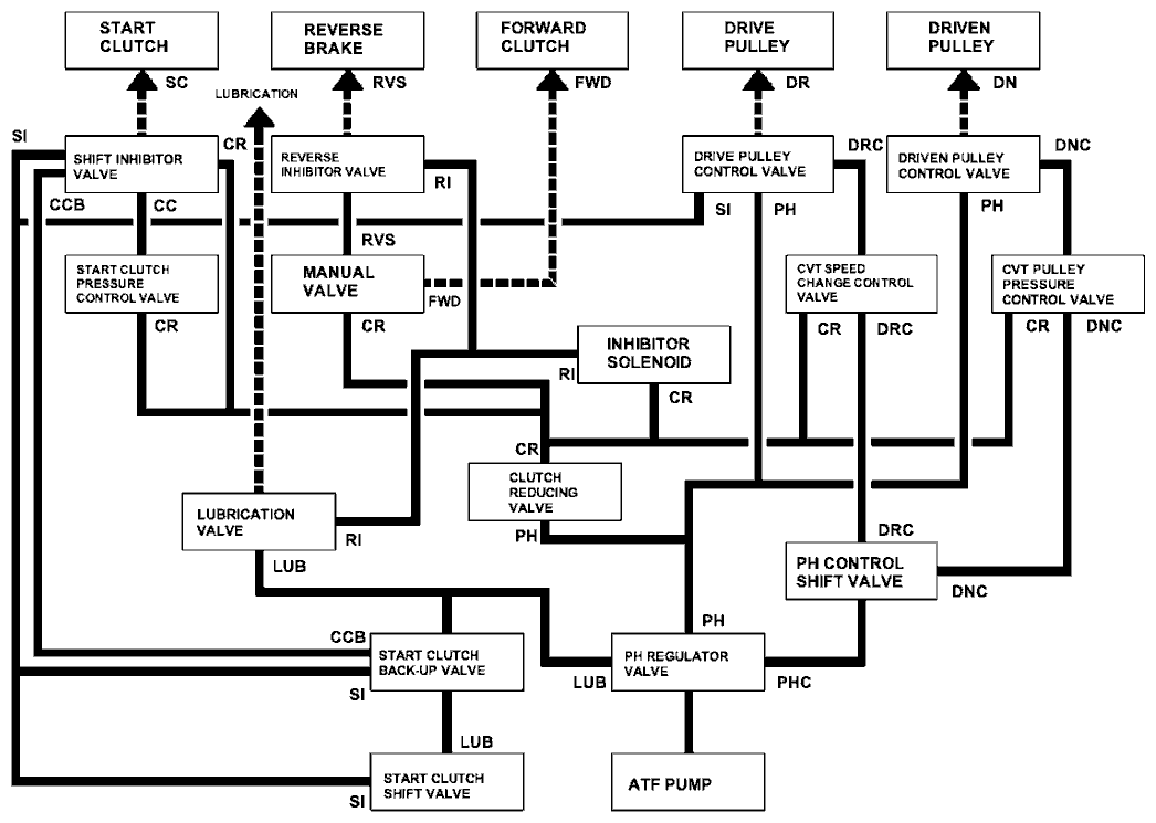
Hydraulic Flow
As the engine turns, the ATF pump starts to operate. Automatic transmission fluid (ATF) is drawn through the ATF strainer and discharged into the hydraulic circuit. Then, ATF flowing from the ATF pump flows to the PH regulator valve and becomes the PH pressure. The PH pressure flows to the pulley control valves and then to the pulleys. The PCM actuates the solenoids to control hydraulic pressure shifting pulley ratios and engaging the start clutch.
Hydraulic pressure at the port is follows:
| Port No. | Description of Pressure | Port No. | Description of Pressure |
|---|---|---|---|
| CC | CLUTCH CONTROL | PH | PRESSURE HIGH |
| CCB | CLUTCH CONTROL B | PHC | PRESSURE HIGH CONTROL |
| COL | ATF COOLER | RCC | RECIRCULATION |
| CR | CLUTCH REDUCING | RI | REVERSE INHIBITOR |
| DN | DRIVEN PULLEY | RVS | REVERSE BRAKE |
| DNC | DRIVEN PULLEY CONTROL | RVS' | REVERSE BRAKE |
| DR | DRIVE PULLEY | SC | START CLUTCH |
| DRC | DRIVE PULLEY CONTROL | SI | SHIFT INHIBITOR |
| FWD | FORWARD CLUTCH | X | DRAIN |
| LUB | LUBRICATION | HX | HIGH POSITION DRAIN |
| LUB' | LUBRICATION | AX | AIR DRAIN |
| LUB'' | LUBRICATION |
Hydraulic Flow (cont'd)
N Position
Fluid from the ATF pump regulates high pressure at the PH regulator valve, and becomes the pressure high (PH) pressure. The PH pressure becomes the clutch reducing (CR) pressure at the clutch reducing valve, and flows to the CVT speed change control valve and CVT pulley pressure control valve. The CVT speed change control valve change the CR pressure to the drive pulley control (DRC) pressure, and supplies the DRC pressure to the PH control shift valve and drive pulley control valve. Likewise, the CVT pulley pressure control valve supplies the driven pulley control (DNC) pressure to the PH control shift valve and driven pulley control valve. The PCM controls the CVT speed change control valve and CVT pulley pressure control valve to regulate the DNC pressure higher than the DRC pressure. The driven pulley receives the driven pulley (DN) pressure higher than the drive pulley (DR) pressure applied to the drive pulley. At this time, the pulley ratio is low.
The manual valve intercepts the hydraulic pressure to the forward clutch, and the shift inhibitor valve intercepts the hydraulic pressure to the start clutch. Under this condition, hydraulic pressure is not applied to the forward clutch, start clutch, and reverse brake.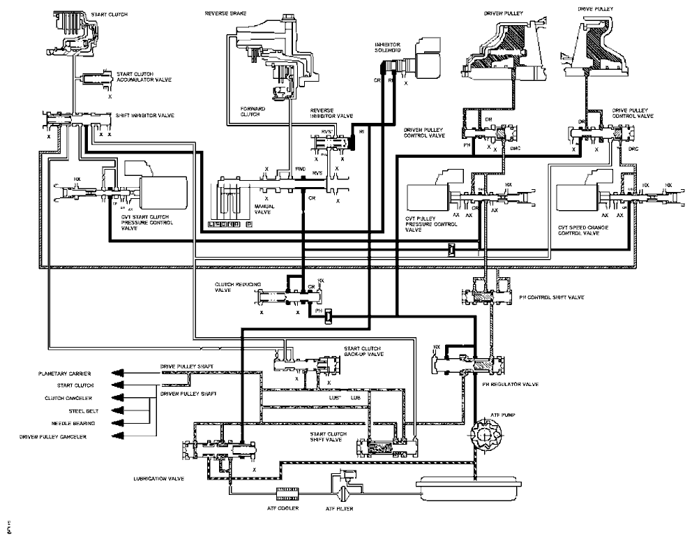
D Position, at low speed range
The fluid flow circuit to the drive pulley and driven pulley is the same as in the N position, and the pulley ratio remains low. The manual valve is shifted in D position, and uncovers the port leading the forward clutch (FWD) pressure to the forward clutch. The FWD pressure flows to the forward clutch, and the forward clutch is engaged. The forward clutch drives the input shaft and drive pulley shaft. The PCM actuates the CVT start clutch pressure control valve to supply the clutch control (CC) pressure to the shift inhibitor valve. The CC pressure becomes the start clutch (SC) pressure at the shift inhibitor valve, and the SC pressure flows to the start clutch. The start clutch is engaged, and the vehicle moves.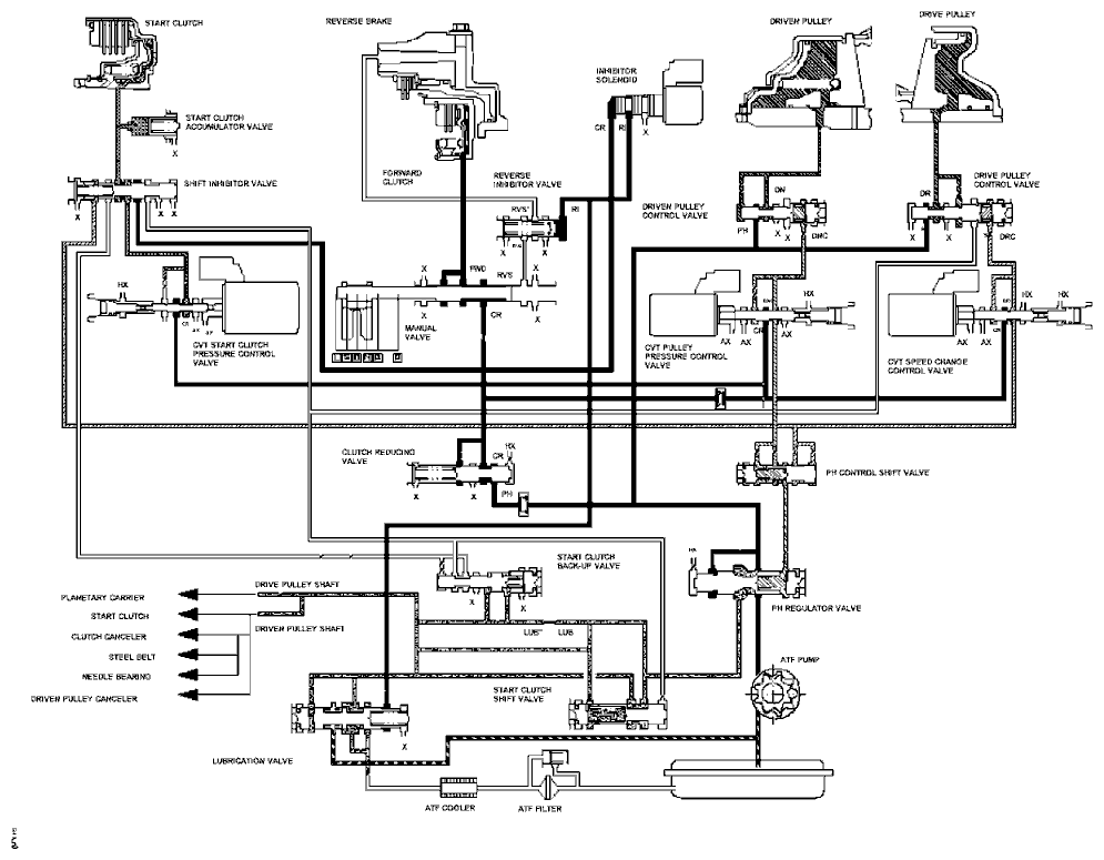
Hydraulic Flow (cont'd)
D Position, at middle speed range
As the speed of the vehicle reaches the prescribed value, the CVT speed change control valve and CVT pulley pressure control valve are activated by the PCM. The CVT speed change control valve regulates the DRC pressure, and the CVT pulley pressure control valve regulates the DNC pressure to apply the same volume of the hydraulic pressure to the pulleys. The drive pulley and driven pulley received same volume pressure apply the same pulley diameter to the steel belt. At this time, pulley ratio is in the middle. Hydraulic pressure remains to apply the forward clutch and start clutch.
D Position, at high speed range
Vehicle speed is further increased, the CVT speed change control valve and CVT pulley pressure control valve controls the DR pressure higher than DN pressure to regulate the DRC and DNC pressure. The drive pulley receives higher pressure than driven pulley received pressure. The drive pulley apply the large pulley diameter to the steel belt, and the pulley ratio is in the high. Hydraulic pressure remains to apply to the forward clutch and start clutch.
Hydraulic Flow (cont'd)
Reverse Inhibitor Control
If the R position is selected while the vehicle is moving forward at speed over 6 mph (10 km/h), the PCM outputs the signal to turn ON the inhibitor solenoid, and the reverse inhibitor (RI) pressure in the right end of the reverse inhibitor valve is released. The reverse inhibitor valve moves to the right side, and covers the port to stop the reverse brake (RVS) pressure to the reverse brake from the manual valve. The RVS pressure is not applied to the reverse brake, and power is not transmitted to the reverse direction.
NOTE: When used, ‘‘left'' or ‘‘right'' indicates direction on the hydraulic circuit.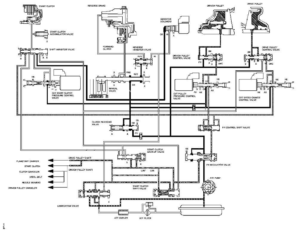
R Position
The manual valve is shifted into the R position, and uncovers port leading the reverse brake (RVS) pressure to the reverse inhibitor valve. The inhibitor solenoid is OFF by the PCM, the reverse inhibitor (RI) pressure is applied to the right end of the reverse inhibitor valve. The reverse inhibitor valve moves to the left side, and uncovers the port leading the RVS' pressure to the reverse brake. The clutch reducing (CR) pressure becomes the RVS pressure, and flows to the reverse brake via the reverse inhibitor valve. The reverse brake is engaged, and it locks the planetary carrier. Hydraulic pressure also applies to the start clutch.
NOTE: When used, ‘‘left'' or ‘‘right'' indicates direction on the hydraulic circuit.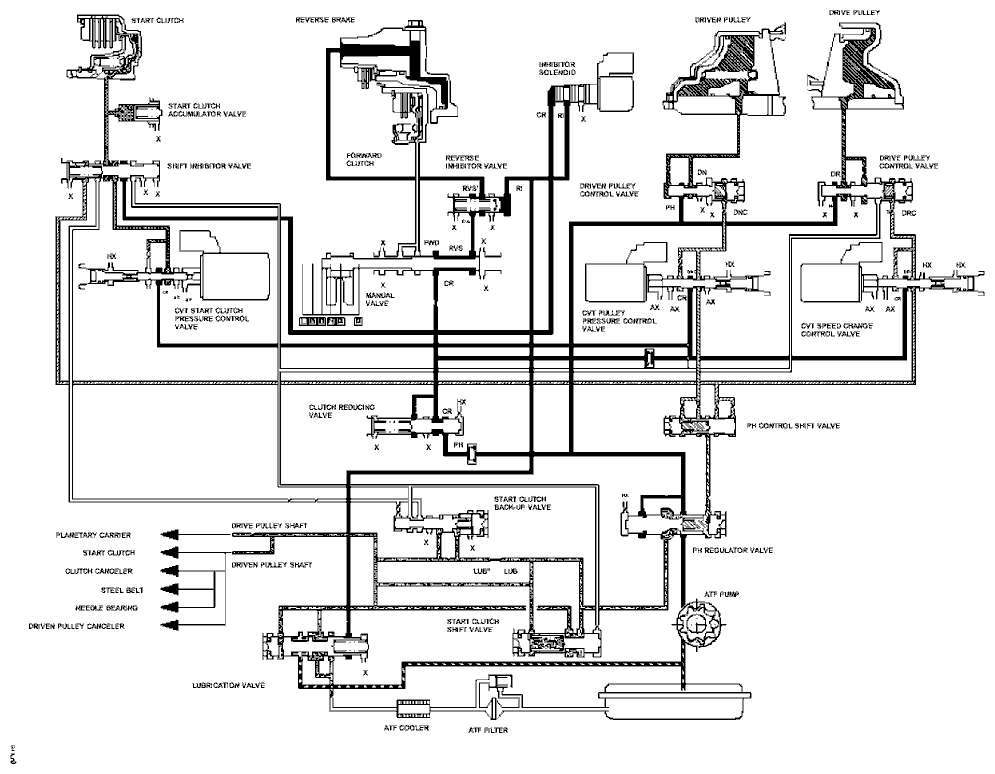
Hydraulic Flow (cont'd)
P Position
The manual valve is shifted into P position, and covers the port leading the hydraulic pressure to the forward clutch and reverse brake. The shift inhibitor valve intercepts the hydraulic pressure to the start clutch. The fluid flow circuit to the drive pulley and driven pulley is the same as in the N position, but the hydraulic pressure is not applied to the forward clutch, start clutch, and reverse brake.
D Position, when an electronic control system breakdown occurs.
When an electronic control system breakdown occurs, the transmission creates temporary fluid flow circuit to allow the vehicle to drive. The drive pulley control (DRC) pressure exceeds a prescribed value at the CVT speed change control valve, the DRC pressure flows to the shift inhibitor valve, and the shift inhibitor valve is moved to the left side. The clutch reducing (CR) pressure from the clutch reducing valve becomes the shift inhibitor (SI) pressure at the shift inhibitor valve. The SI pressure flows to the start clutch shift valve and start clutch back-up valve, and becomes to the clutch control B (CCB) pressure at the start clutch back-up valve. The CCB pressure becomes the start clutch (SC) pressure at the shift inhibitor valve, and the SC pressure flows to the start clutch. The start clutch is engaged, and the vehicle can move.
NOTE: When used, ‘‘left'' or ‘‘right'' indicates direction on the hydraulic circuit.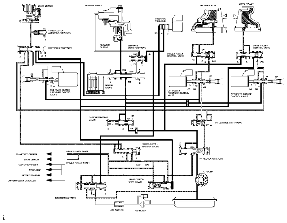
Hydraulic Flow (cont'd)
R Position, when an electronic control system breakdown occurs.
When an electronic control system breakdown occurs, the transmission creates temporary fluid circuit to allow the vehicle to drive. The fluid flow circuit to the reverse brake is the same a in the R position, and the reverse brake is engaged. The drive pulley control (DRC) pressure exceeds a prescribed value at the CVT speed change control valve, the DRC pressure flows to the shift inhibitor valve, and the shift inhibitor valve is moved to the left side. The clutch reducing (CR) pressure from the clutch reducing valve becomes the shift inhibitor (SI) pressure at the shift inhibitor valve. The SI pressure flows to the start clutch shift valve and start clutch back-up valve, and becomes to the clutch control B (CCB) pressure at the start clutch back-up valve. The CCB pressure becomes the start clutch (SC) pressure at the shift inhibitor valve, and the SC pressure flows to the start clutch. The start clutch is engaged, and the vehicle can move.
NOTE: When used, ‘‘left'' or ‘‘right'' indicates direction on the hydraulic circuit.
Park Mechanism
The park mechanism locks the transmission by engaging the park pawl with the park gear which is integral with the secondary drive gear. The secondary drive gear engages with the secondary driven gear which is splined with the final drive shaft, and the final drive gear which is integral with the final drive shaft engages the final driven gear. Shifting to P position causes the park cone (installed at the end of the park rod) to press the park pawl onto the park gear. Even if the end of the park pawl rides on the top of the park gear teeth, slight movement of the vehicle will cause the park pawl and park gear to mesh with each other completely because the park cone receives the tension from the park rod spring. The park pawl receives the tension (which acts to separate the park pawl from the park gear) from the park pawl spring.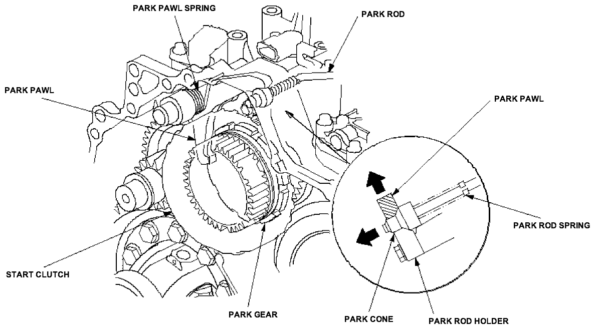
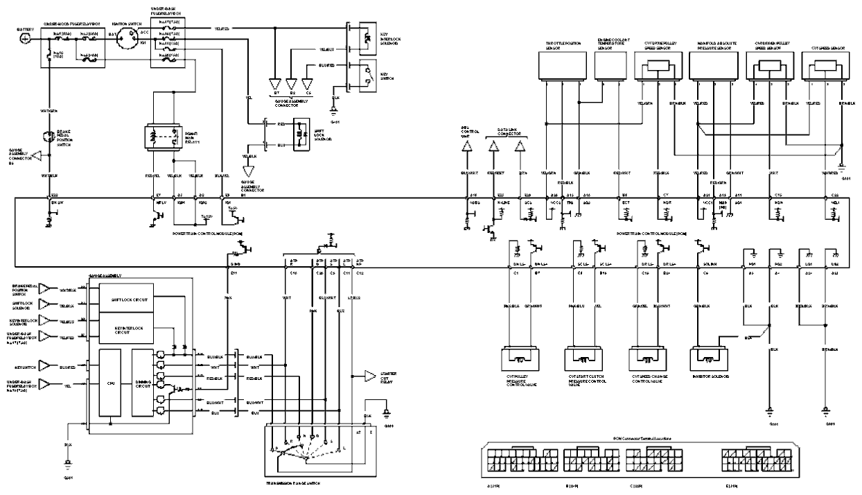
Circuit Diagram